
| Model | B1DH-Q | B1DF | SPP-T | B1D-FR |
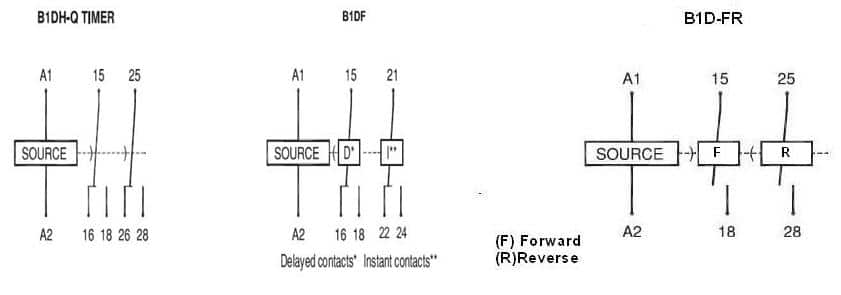
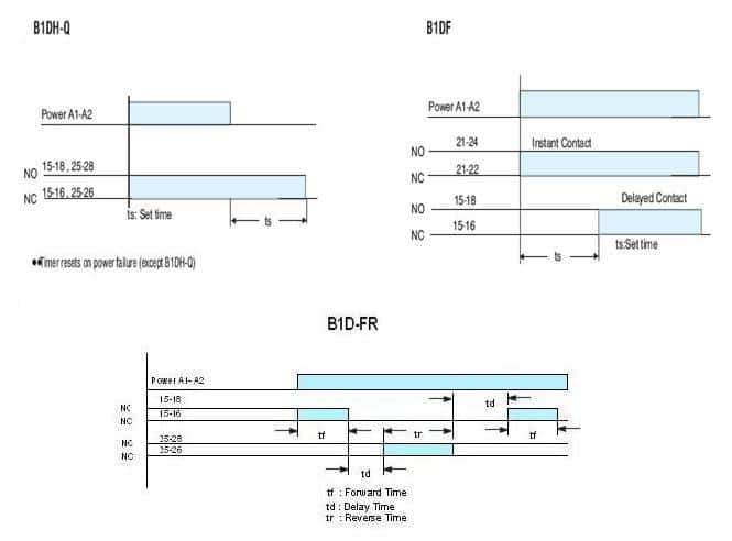
| Function | Power Off-Delay | On-Delay with instant contact | Phase Unbalance, Phase Failure, Negative Phase Sequence Monitor & Contol | Switch two Loads with delay in between in cyclic fashion |
| Rated supply voltage | 110V AC to 240V AC 110V DC to 220V DC | 24V DC 240V AC
| 415V AC, 3 phase | 240V AC |
| Operation Voltage Range | -20% to +10% of rated voltage | -10% to +10% of rated voltage(For 24V DC) – 20% to +10% of rated voltage(For 240V AC) | -65% to +20% of rated voltage | -20% to +10% of the rated voltage |
| Rated frequency | 50 / 60Hz ± 5% | 50Hz ± 5% | ||
| Trip Time Delay | N.A | N.A | Unbalance: 2.5 sec max , Unbalance response :10% ± 3% ,Phase failure:2 sec max | N.A |
| Control relay output | 2 c/o rated for 5A @ 250V AC / 28V DC resistive load | 1 c/o Rated for 5A @ 250V AC / 28V DC resistive load | ||
| Mode of Operation | N.A | Auto / Manual | N.A | |
| On delay time | N.A | 30 Sec ± 4 Sec (Auto mode) | N.A | |
| Power consumption | 150mA peak current, 5mA once stabilized. | AC approx. 15VA / 3W (FOR 240V AC) Approx. 2W(FOR 24V DC) | AC approx.34VA / 7W | AC approx.30VA |
| Time range | 6Sec – 60 Sec | 0.3Sec – 30Min | N.A | Forward & Reverse 0.6Min to 6Min, Delay 0.1 Min to 1Min |
| Range selection | N.A | 3S, 30S, 3M, 30M | N.A | N.A |
| Setting accuracy | ± 10% max. w.r.t full scale ± 100mSec | N.A | ± 10% max. w.r.t full scale ± 100mSec | |
| Repeat accuracy | ± 2% max. ± 100mSec | ± 1% max. ± 100mSec | N.A | ± 1% max. ± 100mSec |
| Recovery time | N.A | 100mSec minimum | 100mSec minimum | 150mSec minimum |
| Minimum energisation time | 1Sec | N.A | N.A | |
| Temperature co-efficient | ± 0.5% max. for every1°C | N.A | N.A | |
| Variation due to voltage change | ± 2% max.± 100mSec | N.A | ± 2% max. ± 100mSec | |
| Variation due to temperature change | ± 5% max.± 100mSec @ 25°C | ± 5% max.± 100mSec | N.A | ± 5% max. ± 100mSec |
| Variation due to frequency change | ± 2% max.± 100mSec | N.A | ± 2% max. ± 100mSec | |
| Ambient temperature | Operation -10ºC to +55ºC, Storage -25ºC to +80ºC | |||
| Humidity | MAX 85% RH@40ºC | |||
| Service life (under no load) | 106 operations minimum | |||
| Electrical life (under full load) | 105 operations minimum | |||
| Rated frequency of operation | 120 ± 5% operations per hour maximum | 1800 ± 5% operations per hour maximum | ||
| Insulation resistance | > 100M ohms@500V DC | |||
| Dielectric strength | 1. 2.5KV AC, 50Hz for 1minute.(Between current carrying & non current carrying parts.) 2. 1.5KV AC, 50Hz for 1minute. (Between contacts & control circuit.) 3. 1KV AC, 50Hz for 1minute. (Between non-continuous contacts of the relay.) | |||
| Electrical connection | Screw type terminals with self lifting clamps | |||
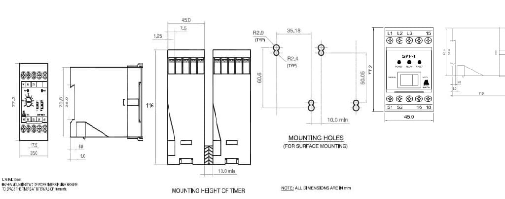
| Dimension | 45 x 75 x 116mm (W x H x D) | |||
| Allowable Ripple | N/A | 3 % maximum(For 24V DC only) | N/A | |
| Enclosure (series) | B1D series | N/A | B1D series | |


Change the positions of respective range selector switches of the timer & rotate the respective pot to get desired ON & OFF time setting with the flat blade screw driver