- LEADING PROVIDER
OF INDUSTRIAL SOLUTIONS
- PRODUCT BEST RATE
- NO. 1 EASTERN INDIA
- LEADING PROVIDER
OF INDUSTRIAL SOLUTIONS
- PRODUCT BEST RATE
- NO. 1 EASTERN INDIA
OF INDUSTRIAL SOLUTIONS
OF INDUSTRIAL SOLUTIONS
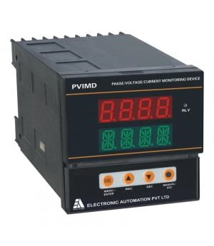
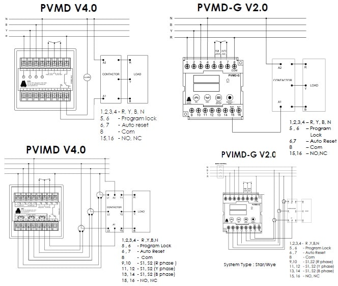
| Model | PVMD | PVMD-G | PVIMD | PVIMD-G |
| Function | Phase Unbalance,Phase Reversal,Phase Failure, Under and Over Voltage, Monitor and Control | Phase Unbalance,Phase Reversal,Phase Failure, Under and Over Voltage, Under and Over Current Monitor and Control | ||
| Input Voltage | 415V AC, 3 phase, 4 wire | |||
| Input Frequency | 50Hz ± 10% | |||
| Input Current | N.A | Current inputs (AR, AY, AB) lb=5A | ||
| Voltage(Accuracy) | ±4V of display value | |||
| Trip Time(Accuracy) | ±1% of set delay of value ±2 sec | |||
| Current(Accuracy) | N.A | ± 5% of lb ± 1 digit (lb=5A) | ||
| Power consumption | 5VA / 1W | |||
| Trip Setting | Phase Unbalance-> 1-20%(Adj.)Under Voltage-> 5 to 100V AC Over Voltage-> 5 to 100V AC | Phase Unbalance-> 1-20%(Adj.)Under Voltage-> 5 to 100V AC Over Voltage-> 5 to 100V AC Over Current-> 105% to 800% Under Current->20%* to 95% | ||
| Minimum sensing current | N.A | 0.5A | ||
| Maximum setting current | N.A | 5A(Above 5A-> Ext.CT can be used, CT setting max.2500/5 in steps of 5) | ||
| Trip time delay | 1 to 250 secs settable for UB, OV, UV | 1 to 250 secs settable for UB, OV, UV, OC, UC | ||
| Phase Failure trip time delay | Less than 5 sec | |||
| Phase reverse trip time delay | Instantaneous | |||
| Power On Delay | 10 sec Max. | |||
| Inrush current delay | N.A | 1 to 60secs settable | ||
| Control output | 1 c/o rated for 10A @ 250V AC / 28V DC resistive load | |||
| Recovery time | 2sec minimum | |||
| Ambient temperature | Operation: -100C to +550C, Storage: -250C to 800C | |||
| Humidity | Max. 85% RH @ 400C | |||
| Service life (under no load) | 106 operations minimum | |||
| Electrical life (under full load) | 105 operations minimum | |||
| Rated frequency of operation | 1800 ± 5% operations per hour maximum | |||
| Insulation resistance | >100M ohms @ 500V DC | |||
| Di-electrical strength | 1. 2.5KV AC, 50Hz for 1minute. (Between current carrying and non-current carrying parts). 2. 1.5KV AC, 50Hz for 1minute. (Between contacts and control circuit). 3. 750VAC, 50Hz for 1minute. (Between non-continuous contacts of the relay). | |||
| Electrical connection | Screw type terminals with self lifting clamps | |||
| Mode of operation | Manual / Auto | |||
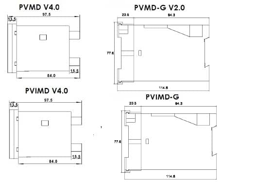
| Dimension (over-all) | 96 x 96 x 97.5 mm (W x H x D) | 76 x 78 x 115 mm (W x H x D) | 96 x 96 x 97.5 mm (W x H x D) | 76 x 78 x 115 mm (W x H x D) |
| * Applicable for more than 2.5 Amps nominal current | ||||
Instruction Manual—–1No
RC Filter—–1No
Tools and Fasteners Kindly use star – type screw driver for tightening the screws.
NOTE: Installation should include a disconnecting device, like switch or circuit breaker, with clear ON/OFF markings, to turn-off the auxiliary
supply (control power).The disconnecting device should be within the reach of the equipment and the operator.